Direct from our Shenzhen automated SMT production facilities: high refresh rate, energy-efficient common cathode architecture, and extreme visual fidelity screens engineered for mission-critical operations.
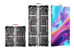
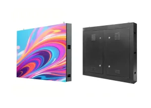
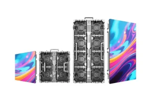
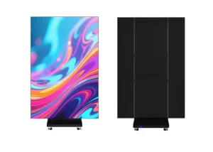
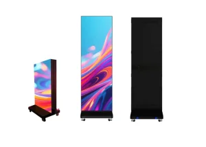
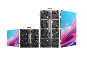
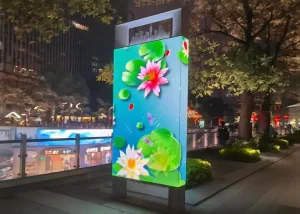
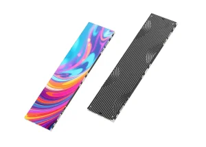
The global visual display landscape is undergoing a structural transformation. Conventional Liquid Crystal Displays (LCDs) and rear-projection cubes have historically dominated mission-critical environments, yet their inherent technological bottlenecks—most notably the visible seam bezels in LCD video walls and the low lumen outputs and lamp degradation of projection engines—have triggered an accelerating transition toward Small Pixel Pitch LED Displays (typically defined as pixel pitches P ≤ 2.5 mm, extending down to ultra-fine MicroLED categories of P0.4 mm to P0.93 mm).
China, and specifically the Pearl River Delta industrial cluster anchored by Shenzhen's Bao'an and Guangming high-tech corridors, manufactures over 85% of the world's fine-pitch LED display volume. This industrial hegemony is not merely a byproduct of assembly line scale; it is fundamentally driven by upstream wafer fabrication, midstream high-precision Surface Mount Technology (SMT) and advanced packaging integration (COB, MIP, GOB), alongside downstream native FPGA controller development.
Modern enterprise procurement directors, broadcast AV architects, and municipal infrastructure integrators are no longer evaluating LED displays simply as digital monitors. Instead, they examine these installations as high-reliability solid-state optoelectronic systems. The criteria have shifted toward critical metrics: thermal dissipation uniformity, optical black state absorption, low-gray scale color linearity, HDR10/HLG compliance, 16-bit PWM grayscale depth, and common cathode power efficiencies. A comprehensive understanding of this manufacturing supply chain is imperative for B2B buyers looking to de-risk high-capital video infrastructure investments.
The technical roadmap for small pixel pitch displays is dictated by the ongoing competition among surface packaging topologies. Choosing the right packaging technology directly determines optical uniformity, field durability, and lifecycle maintenance expenditures.
Traditional packaging where RGB dies are packaged in individual resin housings (e.g., SMD 1010, 0808) and soldered onto the PCB. Highly mature, cost-effective for pitches from P1.5 to P2.5, but physically vulnerable to external impacts, electrostatic discharge (ESD), and high pixel failure rates at pitches below 1.2mm.
An intermediate protective innovation where standard SMD modules are covered with an optically transparent epoxy resin barrier. Provides IP54/IP65 surface protection, dust resistance, collision immunity, and moisture resistance, making it an excellent choice for portable posters, high-traffic commercial displays, and touring installations.
Bare flip-chip LED micro-dies bonded directly to the PCB carrier board and encapsulated with specialized optical black epoxy. Eliminates wire bonding, cuts solder point failure rates by 90%, enables deep pitch scaling (P0.4–P1.2), provides contrast ratios exceeding 10,000:1, and dissipates heat with superior efficiency.
Micro-scale semiconductor dies pre-tested and packaged into ultra-compact, pixel-level surface mount carriers before final assembly. MIP merges the testability, color-binning yield, and single-pixel field serviceability of SMD with the visual uniformity, high contrast, and microscopic pixel pitches characteristic of true MicroLED architectures.
| Packaging Architecture | Available Pixel Pitch (mm) | Surface Protection Rating | Contrast Ratio | Thermal Dissipation Yield | Recommended Core Applications |
|---|---|---|---|---|---|
| SMD (Standard SMT) | P1.25 – P2.5 | Low (Exposed Solder Joints) | 3,000:1 to 5,000:1 | Moderate (Copper Trace Rely) | Meeting Rooms, Auditoriums, Houses of Worship |
| GOB (Protective Polymer) | P1.25 – P2.0 | High (Anti-Impact, Waterproof IP54) | 4,000:1 to 6,000:1 | Moderate to Good | Commercial Posters, Low-Height Retail, Touch Walls |
| COB (Flip-Chip Integrated) | P0.4 – P1.25 | Ultra-High (Epoxy Hermetic Shield) | 10,000:1 to 30,000:1 | Superior (Direct Aluminum Substrate) | Command & Control, Telepresence, 8K Displays |
| MIP (Micro-LED Hybrid) | P0.6 – P1.5 | High (Optical Matrix Coated) | 8,000:1 to 20,000:1 | High (Decentralized Die Dissipation) | Broadcast Studios, Virtual XR, High-End Boardrooms |
Small pixel pitch displays are engineered to operate continuously (24/7/365) across demanding commercial, government, and specialized environments without latency, degradation, or pixel failure.
Government emergency response operations (EOCs), military command hubs, transportation monitoring networks (air traffic, railways), and smart city utility grids demand zero visual interruption. Here, displays with P0.93 to P1.56 pitches provide continuous 24/7 uptime. Integrating dual-loop redundant signal failover, secondary power supplies, and DCI-P3 wide color gamuts ensures real-time GIS mapping, telemetry arrays, and multi-window IP stream decodes stay perfectly clear and free of frame tears.
Cinema production and live broadcast environments are abandoning green screens in favor of Extended Reality (XR) LED stages. These demanding applications require sub-P1.9 pixel pitches, scan rates of 1/8 or 1/16, high refresh rates of 7680Hz, and camera-tracked framerates up to 240fps. This configuration completely eliminates scan-line artifacts, rolling shutter bands, and moiré patterns under modern high-resolution cinema lenses.
Modern corporate boardrooms require clean, seamless digital workspaces without complex projector calibrations or the visible crosshair bezels of LCD matrices. All-in-one smart LED displays (108", 136", 163", and 217" with native 4K resolution) provide wide 170-degree horizontal and vertical viewing angles, integrated audio drivers, wireless multi-device projection, and touch interactivity, creating productive environments for hybrid corporate communication.
Clinical presentation suites and surgical observation centers rely on accurate grayscale gradation. Specialized COB small pixel pitch displays calibrated to DICOM Part 14 standards present clean, noise-free visualization of MRI scans, CT reconstructions, and microscopic surgical imaging, ensuring micro-level contrast without blooming or backlighting artifacts.
Tier-1 retail stores along high-fashion avenues use ultra-high-definition fine pitch LED video walls to engage customers. Displaying rich, true blacks, precise 16-bit color accuracy, and micro-textures of textiles, jewelry, and luxury watches, these displays operate comfortably in bright ambient daylight without washed-out visuals or glare.
Financial trading floors, cybersecurity command centers, and defense telemetry installations require pristine display performance. Fine-pitch displays paired with hardware-isolated FPGA video processors protect classified data feeds from external interception while presenting complex, dense data visual arrays with pixel-level clarity across expansive, seamless video walls.
A high-performance LED display is an engineered system of structural, electrical, and optical subcomponents. JINGRUNS manufactures each cabinet assembly to meet tight tolerances, balance thermal loads, and maintain stable signal transmission.
Fine pixel pitches require strict structural precision. Modular cabinets are manufactured using high-precision CNC die-cast aluminum frames engineered to mechanical tolerances of ≤ 0.01 mm. This dimensional control prevents uneven gaps, panel offsets, and seam lines across massive 8K and 16K video walls.
Traditional common anode systems supply a single voltage (e.g., 3.8V–5V) to red, green, and blue diodes, dissipating excess energy as heat through the red die. Our advanced common cathode power supplies feed independent voltages (e.g., 2.8V for red, 3.8V for green/blue), reducing overall operating temperatures by 15°C to 20°C, cutting power consumption by 35%–40%, and significantly extending LED service life.
Excessive or uneven heat causes thermal expansion, which distorts cabinet alignment and accelerates diode wavelength shift (causing green and pink tint patches). Our fanless chassis design routes heat through integrated aluminum convection paths, eliminating mechanical acoustic noise and preventing hot spots to ensure consistent color temperature across the entire wall.
Standard LED displays often suffer severe grayscale loss and color banding when brightness is dialed down to indoor levels (100–300 nits). Our custom driver ICs with high-order PWM processing preserve a full 16-bit grayscale depth even at 10% brightness, delivering accurate color tracking and shadow gradation without contouring.
Critical systems cannot afford blackouts. JINGRUNS displays support dual receiver cards, secondary signal paths, and hot-swappable parallel power modules. If an active fiber-optic feed or DC bus fails, the backup signal pathway engages within ≤ 2 milliseconds, preventing human-detectable visual dropouts.
Tight architectural spaces, recessed boardroom walls, and control room bridges rarely accommodate rear maintenance clearance. Our modules use magnetic alignment fixtures that enable front-access service using specialized electronic vacuum extraction tools. Technicians can swap out an LED module or power supply in under 60 seconds without dismantling adjacent structural cabinets.
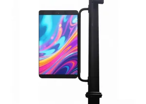
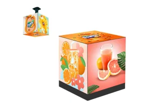
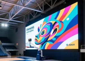
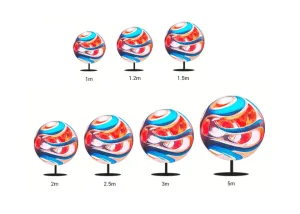
Explore our specialized portfolio: fine-pitch fixed installations, spherical and cube geometries, smart 5G connected infrastructure, and high-impact commercial video solutions manufactured in Shenzhen, China.
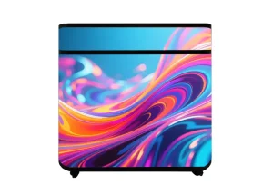
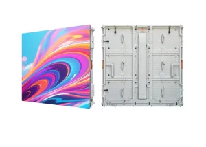
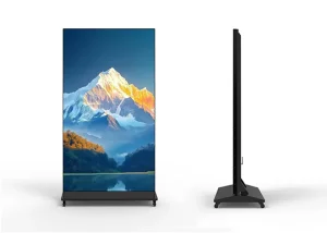
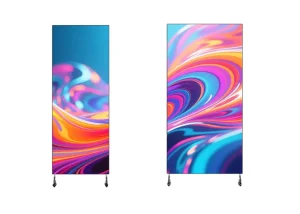
Purchasing fine-pitch LED display walls directly from Shenzhen manufacturers delivers clear cost advantages, but distinguishing true SMT manufacturing facilities from trading agents requires strict engineering verification.
Confirm whether the supplier operates cleanroom-certified SMT pick-and-place lines (e.g., high-speed ASM, Panasonic, or Fuji machines) alongside multi-zone nitrogen reflow ovens, or merely sources assembled modules from third parties. True in-house manufacturing guarantees direct control over PCB solder paste thickness (via 3D SPI) and component placement tolerances (via Automated Optical Inspection - AOI).
Early component failures follow the standard semiconductor bathtub curve. Qualified factories subject 100% of LED modules to a rigorous 72-hour aging and stress test: 24 hours at peak white balance, 24 hours cycling across individual RGB patterns, and 24 hours under dynamic high-contrast video sequences with temperature cycling. Request live video audits and batch test documentation.
LED wafer micro-diodes naturally vary in forward voltage, wavelength, and luminous intensity. Sourcing panels manufactured across mixed wafer batches creates noticeable mosaic and patchiness across the video wall. Reputable manufacturers guarantee Single-Bin Sorting alongside per-pixel optical calibration (chroma and luma calibration) across the entire order.
Small pixel pitch screens require professional video processors and receiver hardware. Leading manufacturers design systems compatible with high-end control platforms such as NovaStar (COEX/Armor Series), Brompton Technology (Tessera), or Colorlight. Verify low-latency 4K/8K @ 60Hz 4:4:4 processing, Genlock synchronization, and full calibration file storage.
Fine-pitch displays generate significant high-frequency harmonics across high-density driver layouts. Poorly isolated cabinets can disrupt surrounding wireless networks and fail local regulatory checks. Insist on genuine test reports for FCC Part 15 Class A/B, CE-EMC Class B, UL 62368-1, CB, and RoHS certified by accredited third-party laboratories.
Because diode luminous efficiency naturally decays over time and production bins evolve, replacing a panel three years later with a different production run can cause noticeable color mismatches. Tier-1 manufacturers secure a 3% to 5% spare module allotment from the identical production batch and guarantee long-term availability of identical driver ICs and power supplies.
In-depth engineering answers to common technical, electrical, and commercial inquiries received by our Shenzhen engineering and export team.